ALL ABOUT DIAPHRAGM WALLS
Cut it, to Seal it !
DIAPHRAGM WALL GRABS
A Diaphragm Wall Grab is an attachment which is an adaptation of the clamshell bucket, used primarily for vertical digging below ground level and for placing materials at considerable height, depth, or distance.
Due to its robust design, numerous extensions and equipment options, the diaphragm wall grab covers a wide range of applications. Equipped with a hydraulically or mechanically operated hose reel system, it can either be deployed with a medium duty cycle crawler crane or a special grab carrier. With the help of an assistant system, deviations can be detected and corrected by the rig operator.
CLASSIFICATION

The Diaphragm Wall Grabs are classified on the basis of the following principal criteria :
1. Mounting Arrangement :
Kelly bar mounted : Rigid mounting helps in superior verticality control but reduced hoisting force, speed and depth range. Extremely useful in areas with limited working space as it enables mounting on a piling rig instead of a bulky expensive crawler rig;
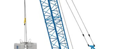
Rope suspended : High hoisting force, speed of operation and unlimited depth range. Requires heavy duty crawler cranes for mounting and can be a constraint in tight spaces within close proximity of neighboring structures.
2. Grabbing Mechanism :
Hydraulic Grab : Hydraulically operated and controlled closing jaws with highest closing forces. Suitable for stiff clay, rocks and dense sands with SPT > 30. Best in class verticality and steering control;
Mechanical Grab : Mechanically operated either via spring or cable tension with low closing forces. Suitable for loose and saturated soils with SPT < 20.
WORKING PRINCIPLE
The grab mimics the structure and operation of the bivalve mollusk, composed of two hinged parts known as the yaws, shells, jaws or shovel set. The working principle of the Diaphragm Wall grab can be summarized into the following events :
The grab free-falls on the soil and the jaws penetrate vertically into the soil due to the weight of the grab. This is called the initial penetration.
The cutting edge follows a certain path through the soil (the digging curve) due to the weight of the grab. During this movement the lower sheave block moves upward and the upper sheave block downward;
The two jaws, rotate around a hinge in the lower sheave block and are connected with the upper sheave block by rods or machined plates;
The closure/hoist cable or kelly bar is reefed between the head and the disc block to generate enough closing force to scoop along the digging curve;
These shells maybe fitted with teeth to gnaw into dense soil and rock, and also have apertures to displace the stabilizing slurry.
In mud the shells in general have flat plates without teeth. In sand, clay and gravel, the shells are fitted in with grabbing teeth. For the removal of contaminated soil closed clamshells are used to avoid spillage.
OPERATION CYCLE
The trenching process is discontinuous and cyclic, consisting of the following activties :
Lowering of the grab to the bottom;
Closing of the grab by pulling the hoisting wire or kelly bar;
Hoisting starts when the bucket is complete closed;
Swinging to the spoils site or hauling vehicle;
Lowering the filled grab bucket into the spoils site or hauling vehicle;
Opening the bucket by releasing the closing wire or kelly bar.
Thus each typical operating cycle can be summarized into the following :
Ease > Dig > Hoist > Swing > Ease > Dump > Hoist > Swing
An operating cycle time between 90s for the first 5m depth is favourable irrespective of the type of soil. An additional 12s of cycle time is added for every additional metre of depth excavated.

KEY COMPONENTS
We shall explore the key components of the most complex Diaphragm Wall Grab, which is hydraulic in nature and composed of :
Annex set
Turning device
Steering flap
Cylinder
Thrust rod
Extension
Cutting edge
Shovel set
Chiseling device
The annex set, turning deice and the steering Flap (1,2 & 3) help in positioning the grab and maintaining its verticality;
The Cylinder and thrust (4 & 5) rod transmit and control the force required to operate the grabs or shells;
The extension (6) as the name suggests is a mounting area to add on incremental weights or shearing blades to increase the inertial force and enhance the trenching operation.
KEY SPECIFICATIONS
1. Choosing the mounting arrangement and grabbing mechanism : Clarity with regards to the mean geological conditions, target productivity required to honor the schedule and working space availability will govern the selection of the mounting arrangement and grabbing mechanism.
2. Choosing the grab : The following criteria influence the selection and performance of the grab :
Width of the diaphragm wall panel : Dictates the width of grab to be employed;
Type of soil : Dictates the amount of closing force and inertial force (function of weight) required for efficient excavation and the requirement of add-ons like chiseling device, cleaning device, type of cutting teeth, type of material of the grab body and teeth etc;
Depth of diaphragm wall : Dictates the thrust capacity of the grab, winch rope diameter and speed, fuel consumption trends and size of the grab to ensure optimal cycle times and minimal idling;
Operational constraints : Constraints wrt the working space availability, concrete availability, permitted working hours, vibration and noise limits can significantly influence the choice of the grab.
SPEC COMPARISON
Due to their versatility and easy adaptability to varying conditions, hydraulic powered rope guided Diaphragm Wall grabs are gaining prominence in the deep excavation industry. Based on our discussion above, let us specify the parameters, which influence the selection of grabs as a function of the width of the Diaphragm Wall panel.

WIDTH RANGE : 300 - 750 MM
Mounting Arrangement : Kelly bar (for depths upto 20m) / Rope suspended;
Grabbing Mechanism : Hydraulic / Mechanical Single or Double winch drum;
Optimal Panel Length : 1800 mm;
Grab capacity : 0.70 - 1.20 m3;
Tare Grab weight : 11.00 - 15.00 t;
Loaded Grab weight : 13.00 - 18.00 t;
Minimum Grab dimensions (L x B x w) : 8800 x 1820 x (w) mm;
Minimum Cylinder closing / Grabbing force : 950 kN @ 27 MPa;
Maximum Grab Opening & Closing Time : 6.0 + 6.4 s;
Minimum Winch / Hoisting speed : 34.50 m/min;
Minimum Grab pull force : 350 kN;
Minimum Base Carrier power : 251 hp @ 1800 rpm;

WIDTH RANGE : 600 - 1200 MM
Mounting Arrangement : Kelly bar (for depths upto 20m) / Rope suspended;
Grabbing Mechanism : Hydraulic / Mechanical Single or Double winch drum;
Optimal Panel Length : 2100 mm;
Grab capacity : 0.90 - 1.80 m3;
Tare Grab weight : 14.50 - 16.50 t;
Loaded Grab weight : 16.50 - 19.50 t;
Minimum Grab dimensions (L x B x w) : 9120 x 2150 x (w) mm;
Minimum Cylinder closing / Grabbing force : 1032 kN @ 30 MPa;
Maximum Grab Opening & Closing Time : 5.4 + 5.7 s;
Minimum Winch / Hoisting speed : 34.50 m/min;
Minimum Grab pull force : 400 kN;
Minimum Base Carrier power : 324 hp @ 2000 rpm;
WIDTH RANGE : 1000 - 1750 MM
Mounting Arrangement : Rope suspended;
Grabbing Mechanism : Hydraulic Single or Double winch drum;
Optimal Panel Length : 2400 mm;
Grab capacity : 1.50 - 2.20 m3;
Tare Grab weight : 19.50 - 30.00 t;
Loaded Grab weight : 22.00 - 35.50 t;
Minimum Grab dimensions (L x B x w) : 10500 x 2550 x (w) mm;
Minimum Cylinder closing / Grabbing force : 1200 kN @ 32 MPa;
Maximum Grab Opening & Closing Time : 5.3 + 5.7 s;
Minimum Winch / Hoisting speed : 34.50 m/min;
Minimum Grab pull force : 500 kN;
Minimum Base Carrier power : 402 hp @ 2000 rpm;
Apart from the criteria outlined above, manufacturers around the globe offer a host of innovative features under their belt. These offer to tackle opportunities related to Safety, Productivity, Ergonomics, Adaptability, QC and autonomous drive. The next section deals with a few of such features which are critical to the operation of constructing Diaphragm Walls.
Additionally, these manufacturers convey the same technical information in different ways particularly drawing heavily on visual content to drive the message home. A sample of one such brochure by the Sany group can be accessed from the following link
FEATURES

ONE SIZE FITS MOST
One Size can Fit Most : Length and Width Extensions which can help maximize return on investment and reduce logistics and space requirements

THE TURNING DEVICE
The hydraulically operated turning device increases maneuverability when working on corner panels or in confined areas.
This helps in eliminating the need for different types of rigs for different work sections. rig positioning is enhanced greatly by allowing their movement either along or at any angle wrt the guide wall alignment.

CUTTING TEETH
Extensive customization in the shape, size and metallurgical characteristics of the cutting teeth for maximum effectiveness in a wide range of soil conditions
VERTICALITY CONTROL
Integration of an inclinometer and a gyroscope on the grab body help in measuring the inclination of the cutter frame continually in both x- and y-axis, and the rotation about its vertical axis.
This ensures continuous and complete control over the trenching operation.

REAL TIME MONITORING DEVICE
A real-time monitoring system fed by a host of sensors help monitor the operational conditions, fuel efficiency, trenching parameters, data logging, generate reports and also offers automation over cyclic activities.

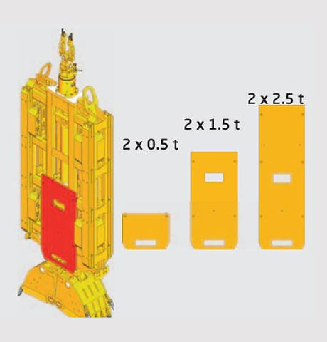
ADDITIONAL WEIGHTS
Additional weights of different sizes can be added if necessary, directly distributing additional weight into the trestle and enhance the inertial force.